

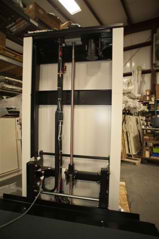
Figure 1
We get a lot of questions about the internals of our wheelchair lifts. We provide these pictures of the internals for your convenience. When planning the installation of a wheelchair lift all types of conditions are encountered. Understanding where the internal mechanisms are placed, and why these locations are chosen can be helpful during the planning stage. Please call our wheelchair lift specialist at 1-800-470-8935 if you have any questions or requests for further information.
In Figure 1 we see the back side of the control tower. This lift is a screw drive model with the brass screw drive shown in the center. There is a motor at the top of the tower with a v belt drive that moves the brass screw drive resulting in the up and down movement of the wheelchair lift's carriage. The motor is mounted at the top of the tower to remove any possibility of water damage under all but extreme flooding conditions.
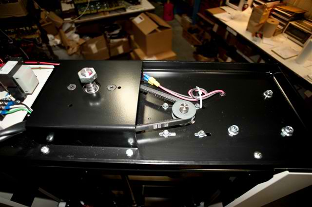
Figure 2
Looking down on the top of the tower we see the V belt pulley (Figure 2) around the top of the screw drive with the motor drive to the left. The top of the wheelchair lift tower covers this entire assembly when completed.
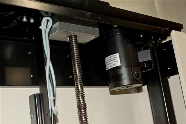
Figure 3
Figure 3 is a view of the underside of the top of the control tower showing the motor to the right of the brass screw drive. The motor spindle runs through the top of the frame with the v belt drive attached as shown in the previous picture.
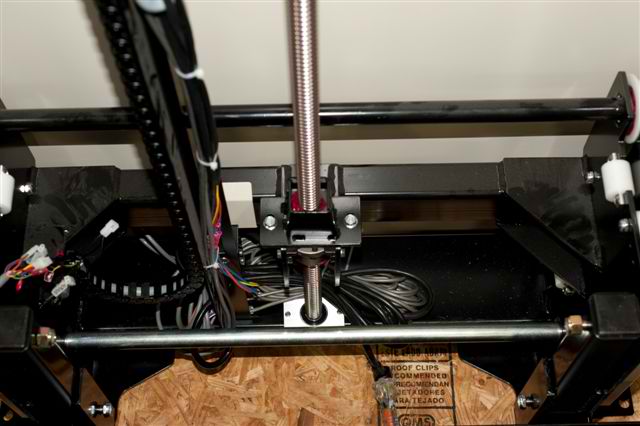
Figure 4
In Figure 4 we are looking down on the brass screw drive showing how the attached carriage is moved up and down. The highest quality wheelchair lifts are all constructed with worm drives. When a wheelchair lift is shipped the tower must be shipped on it's side. A color changing package is attached to the crate which changes to red if the crate is moved from the horizontal position. On tall towers the worm drive shown can be bent if mis-handled during shipping. You can see here why the spindle must be completely straight.
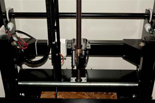
Figure 5
This is a closer view (Figure 5) of the screw drive assembly at the lower position.
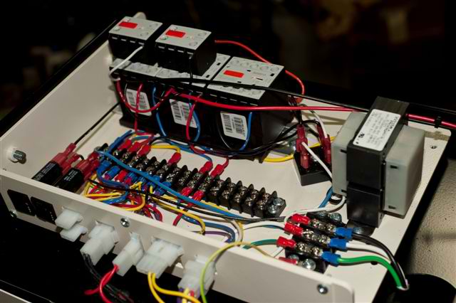
Figure 6
Figure 6 shows the electrical control box assembly which is ultimately enclosed during final assembly.